Hardware Setup - Part 1
Once you have installed the software and the device drivers, the next step is to set up the hardware.
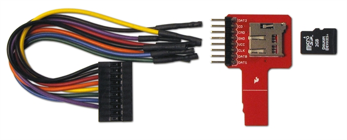
Provided with the Frontline SD hardware is one of two Secure Digital (SD) Input/Output (IO) adapters: 1) the standard SD card adapter, and 2) the micro SD card adapter. Provided with each is a cable that must be connected to the adapter prior to the connecting the adapter to the Frontline SD hardware. The following tables lists the Frontline SD Hardware pinout, with corresponding cable color-code and the adapter pinout. In addition the table shows the pin designation for the SD 4-bit and 1-bit high-speed mode and the SPI mode.
| Pin | SD 4-bit Mode | SD 1-bit Mode | SPI Mode | |||
|---|---|---|---|---|---|---|
| 1 | CD/DAT3 | Data Line 3 | - | - | CS | Card Select |
| 2 | CMD | Command Line | CMD | Command Line | DI | Data Input |
| 3 | VSS1 | Ground | VSS1 | Ground | VSS1 | Ground |
| 4 | VDD | Supply Voltage | VDD | Supply Voltage | VDD | Supply Voltage |
| 5 | CLK | Clock | CLK | Clock | SCLK | Clock |
| 6 | VSS2 | Ground | VSS2 | Ground | VSS2 | Gound |
| 7 | DAT0 | Data Line 0 | DATA | Data Line | DO | Data Output |
| 8 | DAT1 | Data Line 1/Interrupt | IRQ | Interrupt | IRQ | Interrupt |
| 9 | DAT2 | Data Line 2/ Read Wait | RW | Read Wait | - | - |

Standard SD Adapter and Cable

Micro SD Adapter and Cable
| Frontline Hardware | Adapter Cable Wire Color | Standard Adapter Pin/Label | Micro Adapter Pin/Label |
|---|---|---|---|
| GND | Black | 4/GND | 4/GND |
| CLK | Brown | 7/CLK | 6/CLK |
| CMD | Red | 3/CMD | 3/CMD |
| DAT0 | Orange | 9/D0 | 7/DAT0 |
| DAT1 | Yellow | 10/D1 | 8/DAT1 |
| DAT2 | Green | 1/D2 | 1/DAT2 |
| CD | Blue | 5/CD | 2/CD |
| Blue* | 5/D3* | - | |
| VDD | Purple | 6/VCC | 5/VCC |
| * 4-bit mode | |||
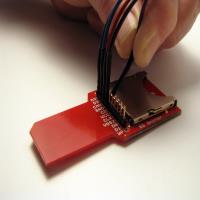
Connect Cable to Adapter
-
 Refer to the SDIO Pinout table and the Frontline SD Adapter Wiring list for the SD mode and adapter you will be using.
 - Identify the wire color associated with the pin on the adaper for the appropriate mode.
- Place the cable wire free end pin over the appropriate pin on the adapter and gently push on until fully seated.
Connect Frontline SD Hardware
-
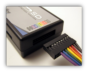
Plug the standard SD card adapter with the connectors into the 10 pin slot of the Frontline SD hardware by matching the color coding on the wires to the label on the hardware .
-
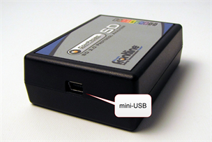
On the other side, attach the USB cable to the USB Mini B receptacle .
That is it for the hardware setup right now. We are not done yet, but after you start the application and make some configurations settings, you will set up the rest of the hardware then. That comes in Hardware Setup – Part 2.

