USB I/O Settings
The IO Settings dialog is used to configure a device. The USB Frontline® filters out a number of packet types by default.
The top of the dialog displays the Firmware and Hardware versions.
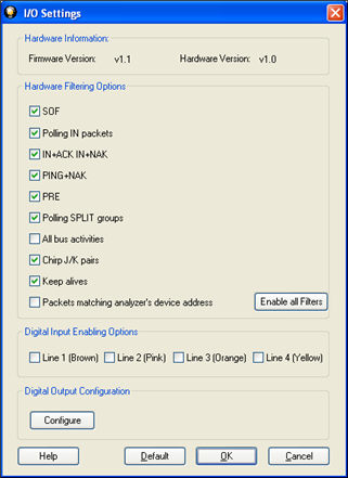
Hardware Input Filter
These options enable the analyzer hardware to discard some common packet groups to reduce the amount of capture data received. Some of these packet groups correspond to polling operations and so these sequences do not contain any actual data transfer. If there is a change in the digital input lines in the middle of one of the packet groups that is being filtered, that group will not be discarded. In this way, the context for the digital input line change is preserved.
- Select I/O Settings from the Options menu on the Control window.
- Select a checkbox
to filter out one or more of the following packets.
- SOF – Discard Start-of-Frame packets. This setting is on by default.
- Polling IN packets
- IN+ACK IN+NAK
- PING+NAK
- PRE – Discard all PRE tokens.
SPLIT – Enabling this option will cause the hardware to discard many polling split packet groups. The split groups that will be discarded are:
- SSPLIT+IN
- SSPLIT+IN+ACK
- CSPLIT+IN+NAK
- CSPLIT+IN+NYET
- CSPLIT+OUT+NYET
- CSPLIT+SETUP+NYET
- All bus activity
- Chrip J/K pairs
- Keep alives
- Packets matching analyzer's device address
- Once you have selected the filters, select Enable all Filters.
Digital Input Enabling Options
Digital inputs provide a means for users to insert events into the data stream. There are four digital inputs that can be enabled individually. Each line is identified by a different color: Line 1 is brown, 2 is pink, 3 is orange, and 4 is yellow.
Whenever an enabled input changes state it will issue an event and be tagged with a timestamp of when the input was interpreted by the analyzer. Digital inputs can not exceed a rate of 30 MHz. Digital inputs that occur faster than that are not guaranteed to be interpreted correctly by the analyzer. Also, only one digital input event may occur per active packet. All other digital input events can only be handled after the packet has finished. Digital inputs, although guaranteed to have the correct timestamp given the previous conditions, may be presented out of order because they are provided randomly by the user and have no direct correlation to the bus. It is important to note that the digital inputs are susceptible to cross-talk if they are not being actively driven. This could occur if a digital input has been enabled, but has not been tied to a signal. Any other nearby signal (i.e., other digital inputs or outputs) could cause the input to activate. We recommend that all undriven digital inputs be disabled or tied to ground.
Note: The raw timestamp value is the number of 100-nanosecond intervals since the beginning of January 1, 1601. This is standard Windows time.
- Select one or more of the Digital Input Enabling Options.
Digital Output Configuration
- Click the
- Select OK to close the
dialog.