USB I/O Settings - Digital Output Configuration
Digital outputs provide a means for users to output certain events to other devices, such as oscilloscopes. In this way, users can synchronize events on the bus with other signals they may be measuring.
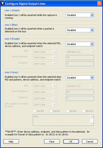
Configure Digital Output Lines
 There are four digital outputs that are user configurable.
Each
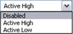
output has the option of being Enabled/Disabled, Active High (voltage),
or Active Low (voltage).
There are four digital outputs that are user configurable.
Each
output has the option of being Enabled/Disabled, Active High (voltage),
or Active Low (voltage).
Furthermore, each output can activate on specific conditions.
- Digital Output 1 Green: asserted whenever the capture is running. Select Enabled/Disabled, Active High (voltage), or Active Low (voltage)
- Digital Output 2 Blue: asserted whenever a packet is detected on the bus. Select Enabled/Disabled, Active High (voltage), or Active Low (voltage)
-
Digital Output 3 Purple: asserted whenever a packet matches the PID, Device Address, and Endpoint values that you select. Select Enable, Active High (voltage), or Active Low (voltage) for Line 3.
- PID: The PID is the first byte of valid data sent
across the bus, and it encodes the packet type. The PID may be followed
by anywhere from 0 to 1026 bytes, depending on the packet type. The PID
byte is self-checking; in order for the PID to be valid, the last 4 bits
must be a one’s complement of the first 4 bits. If a received PID fails
its check, the remainder of the packet will be ignored by the USB device. Select Don't
Care, Is Equal to, or Is Not Equal to from the PID drop-down list
.
- If you select Is Equal to or Is Not Equal to for line 3, choose a Packet Identifier (PID value from the drop-down list.
-
Device Address: Select Don't Care, Is Equal to, or Is Not Equal to from the drop-down list for the Device Address..
- If you select Is Equal to or Is Not Equal to enter a value for the Device Address.
- The Device Address must be entered in Hexadecimal. The range is 00‑7F.
-
Endpoint: The endpoint is the fundamental unit of communication in USB. All data is transferred through virtual pipes between the host and these endpoints. All communication between a USB host and a USB device is addressed to a specific endpoint on the device. Each device endpoint is a unidirectional receiver or transmitter of data; either specified as a sender or receiver of data from the host. Select Don't Care, Is Equal to, or Is Not Equal to from the Endpoint drop-down list.
- If you select Is Equal to or Is Not Equal to enter a value for the Endpoint.
- The Endpoint must be entered in Hexadecimal. The range is 0‑F.
- PID: The PID is the first byte of valid data sent
across the bus, and it encodes the packet type. The PID may be followed
by anywhere from 0 to 1026 bytes, depending on the packet type. The PID
byte is self-checking; in order for the PID to be valid, the last 4 bits
must be a one’s complement of the first 4 bits. If a received PID fails
its check, the remainder of the packet will be ignored by the USB device. Select Don't
Care, Is Equal to, or Is Not Equal to from the PID drop-down list
.
-
Digital Output 4 Gray: asserted whenever a packet matches the PID, Data Pattern, Device Address, and Endpoint values that you set. Select Enable, Active High (voltage), or Active Low (voltage) for Line 4.
- PID: Select Don't
Care, Is Equal to, or Is Not Equal to from the PID drop-down list
.
- If you select Is Equal to or Is Not Equal to for line 3, choose a Packet Identifier (PID value from the drop-down list.
- The PID may be followed by anywhere from 0 to 1026 bytes, depending on the packet type. The PID byte is self-checking; in order for the PID to be valid, the last 4 bits must be a one’s complement of the first 4 bits. If a received PID fails its check, the remainder of the packet will be ignored by the USB device.
-
Device Address: Select Don't Care, Is Equal to, or Is Not Equal to from the drop-down list for the Device Address..
- If you select Is Equal to or Is Not Equal to enter a value for the Device Address.
- The Device Address must be entered in Hexadecimal. The range is 00‑7F.
-
Endpoint: The endpoint is the fundamental unit of communication in USB. All data is transferred through virtual pipes between the host and these endpoints. All communication between a USB host and a USB device is addressed to a specific endpoint on the device. Each device endpoint is a unidirectional receiver or transmitter of data; either specified as a sender or receiver of data from the host. Select Don't Care, Is Equal to, or Is Not Equal to from the Endpoint drop-down list.
- If you select Is Equal to or Is Not Equal to enter a value for the Endpoint.
- The Endpoint must be entered in Hexadecimal. The range is 0‑F.
-
Data pattern to match (in Hex): You can specify data match pattern for Line 4, as well as which data packets to match. Select Don't Care, Is Equal to, or Is Not Equal to from the Data pattern to match (in Hex)drop-down list.
-
If you select Is Equal to or Is Not Equal to, select one or more of the data patterns checkboxes.
- DATA0
- DATA1
- DATA2
- MDATA
-
Enter a hex value in the text box.
- Every data packet with the specified PID will have its data payload matched against as much of the pattern as the data payload size. So a data packet with an 8-byte data payload will be compared against the first 8 bytes of the data match pattern. And a data packet with a 64-byte payload will be compared against the first 64 bytes of the data pattern. The data match pattern can be up to 1024 bytes in length.
- You must enter the data pattern in hexadecimal. For example A1 2B 01or A1‑2B‑01.
-
- PID: Select Don't
Care, Is Equal to, or Is Not Equal to from the PID drop-down list
.
Click OK to save the settings and exit the dialog. The Clear button is used to clear all settings in the dialog.