Hardware Description
The Frontline USB hardware is used for external data monitoring. The Frontline USB protocol analyzer is a high speed, full speed, and low speed USB 2.0 system that captures and sends data to the analysis PC over a high speed USB 2.0 connection.
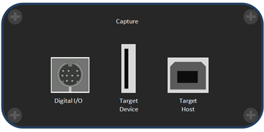
The front of the analyzer has three USB connections: one for the device being tested, one for the PC the device being tested is normally connected to, and one digital I/O port.
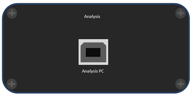
The back panel has one USB connection labeled Analysis PC for connecting the Frontline USB hardware to the computer running Frontline software.
There are three LED’s on top of the Frontline USB .

- The orange LED (TST) serves as a Capture Port connection indicator. It glows when the Target Host is connected.
- The red LED (ACT) indicates bus activity.
- The yellow LED (PWR) serves as an Analysis Port connection indicator. The PWR LED will be illuminated when the analyzer has been correctly connected to the analysis computer and is receiving power from the USB.
The Capture side also includes a mini-DIN 9 connector which serves as a connection to the
digital inputs and outputs. Its pin outs and the cable coloring for the included cable are described in
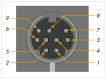
| Pin Name | Color | Pin Number |
|---|---|---|
| Input 1 | Brown | 1 |
| Input 2 | Red | 2 |
| Input 3 | Orange | 3 |
| Input 4 | Yellow | 4 |
| Output 1 | Green | 5 |
| Output 2 | Blue | 6 |
| Output 3 | Purple | 7 |
| Output 4 | Grey | 8 |
| Ground | Black | 9 |
The Frontline USB is powered from the USB port of the analysis computer and doesn't require an external power source.