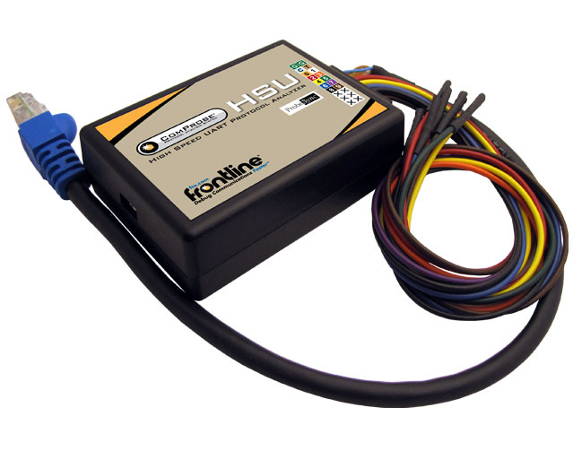
Connect the Frontline HSU to the Device Under Test
The Frontline HSU hgardware is designed for use with TTL voltage levels, 0 to 5 volts max (exceeding the 5.0 volts max damages the Frontline hardware). The Frontline HSU hardware interprets 0 to 0.8 volts as a logical zero, and 2.0 to 5.0 volts as a logical one. To ensure accurate data collection and proper operation, connect the Frontline HSU to the TTL side of any transceivers, line drivers, or line receivers.
Use the table below to determine the connection configuration you need for monitoring signals on the source device. Disconnecting and reconnecting the wires in a different configuration negates the validity of the following table. To avoid confusion, we recommend that you maintain the color code as expressed in this table.
Only "Data Connection" and "Ground" need to be connected, all the other signals are optional.
When using the HSU unit in conjunction with ProbeSync enabled Frontline devices, the HSU CAT 5 cable must be connected to the Frontline device providing the synchronizing clock. Connect the HSU CAT 5 connector to the synchronizing device OUT connector.
The table below provides information on the ProbeSync CAT 5 cable RG-45 connector pin out.
| Wire Label | Label/Wire Color | Signal | Meaning |
|---|---|---|---|
| G | Green | Ground | Ground |
| G | Green | ProbeSync Ground | ProbeSync Ground (CAT 5) |
| C | Blue | ProbeSync Clk | CLOCK_OUT_P of Master (CAT 5) |
| T | Brown | ProbeSync Clk | CLOCK_OUT_N of Master (CAT 5) |
| 0 | Orange | ProbeSync Link | LINK_OUT of Master (CAT 5) |
| 1 | White/Orange stripe | ProbeSync Clk Select | CLOCK_SELECT of Master (CAT 5) |
| 2 | Red | CH0 | Data Connection (TX) |
| 3 | Orange | CH1 | Data Connection (RX) |
| 4 | Yellow | RTS | Request to send |
| 5 | Green | CTS | Clear to send |
| 6 | Blue | DSR | Data Set Ready |
| 7 | Purple | DTR | Data Terminal Ready |
| 8 | Black | CD | Carrier Detect |
| 9 | Brown | RI | Ring Indicator |
| Wire Label | Label Wire Color | Signal | Meaning |
|---|---|---|---|
| 0 | Black | CH 0 | Data Connection |
| 1 | Brown | CH 1 | Data Connection |
| 2 | Red | RTS | Request to Send |
| 3 | Orange | CTS | Clear to Send |
| 4 | Yellow | DSR | Data Set Ready |
| 5 | Green | DTR | Data Terminal Ready |
| 6 | Blue | CD | Carrier Detect |
| 7 | Violet | RI | Ring Indicator |
| TRG | White | Not Used | N/A |
| CLK | Gray | Not Used | N/A |
| GND | Black | Ground | Ground |