Logic Signals in the Frame Display
When analyzing Logic Signals captured using the Sodera HCI pods, the Frame Display presents in the Summary pane a frame that contains one packet with two logic signals from HCI POD 1, followed by a frame with containing one packet from with two logic signals from HCI POD2, if used. The timestamp for these two frames is identical.
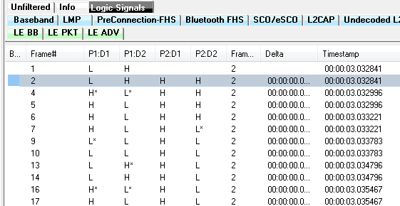
In "Example: Logic Signals Starting Sequence", Frame# 1 shows logic levels for P1:D1 and P1:D2 but P2:D1 and P2:D2 contain no data. This first frame contains a packet with logic data for POD1. In the next frame—Frame# 2—note that P1:D1 and P1:D2 contain the same logic as in Frame#1, and this data is a copy of the preceding Logic Signals frame—Frame 1—providing continuity in the Summary pane display. New data, P2:D1 and P2:D2, appear having been captured from HCI POD2.
This sequence will continue: Frame# 4 P1:D1 and P1:D2 contains new data from POD1 with P2:D1 and P2:D2 containing data from the preceding frame—Frame#2.
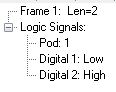
When viewing Frame#1 data in the Decoder pane, only POD1 data is shown.
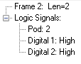
As explained above, in Frame# 2, only new data from POD2 is contained in this packet, and the preceding frame POD1 data is a copy for Summary pane display only. Frame#2 contains only POD2 data.
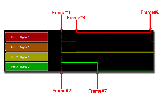
In "Example: Logic Signals from Frame Display Frame#1 to Frame#9", logic signals from Frame#1 through Frame#9 are shown with the signal labels on the left. The first signal transition occurs on both signal lines for POD1 at Frame# 4. The second transition occurs at Frame# 7 on Pod2:Digital 2 (P2:D2). The last transiton occurs at Frame# 9.