Rear Panel Connectors
The rear panel is shown below. The panel provides connectors for external power, ProbeSync™, HCI, and for connection to the computer hosting the Frontline software.
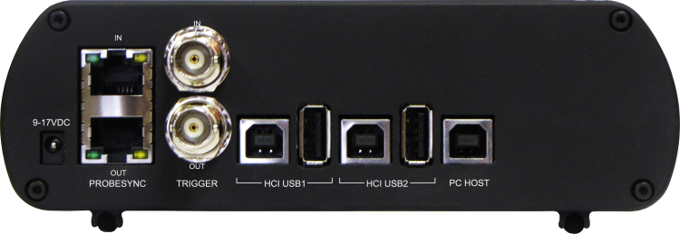
+12VDC: Connection to the Frontline supplied AC-to-DC power adapter, or a 12 VDC auxiliary vehicle outlet system can be used.
ProbeSync™ IN/OUT: Used for synchronizing multiple capture devices. Sodera can act as a clock source (master) device providing the clock to synchronize timestamping with connected target (slave) devices. When operating as a master device the OUT RJ-45 connector provides the synchronizing clock. The synchronizing clock can be attached to a slave Frontline Sodera or a Frontline 802.11, for example. When operating as a slave device, the IN RJ-45 connector receives the synchronizing clock from a master Sodera unit.
HCI USB 1/HCI USB 2:USB Type B and a USB Type A connectors allow capture of HCI USB data. HCI USB 1 and HCI USB 2 are independent groupings of the Type A and Type B connectors. The HCI USB 1 connectors use the same Sodera unit internal interface as the Sodera HCI POD1 UART pins. Likewise the HCI USB 2 connectors use the same internal interface as the Sodera HCI POD2 UART pins. Therefore you cannot simultaneously capture USB and UART on the "1" interface or on the "2" interface. Refer to "Connecting for USB Capture" and to "Connecting for HCI/WCI-2 & Logic Capture".
PC HOST : USB 2.0 port for connecting Sodera to the host computer where the Frontline software resides. This connector provides host computer command, control, and data transfer.
Note: At this time all other rear panel connectors are inactive.