Logic Signals in Timeline View
A logic signal timeline is shown as a high/low representation of the captured signal. A high level appears beginning at the time when the captured signal transitioned from a low state up through the logic-high threshold voltage. The high state is shown at the row label top edge. The logic low state occurs when the captured logic signal transitions from a high state down through the logic-high threshold voltage. A logic low state is shown at the row label bottom edge. State transition is displayed as instantaneous.
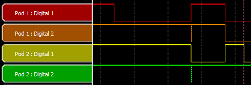
Example: Logic State Transition
The high level threshold is determined by the HCI POD LIO LVL voltage. The minimum threshold voltage is 1.65 Vdc. Refer to "Logic Event Capture Configuration" for more information about the threshold level.