802.11 WiFi Conductive Testing
“Conductive” in this context means that you are not “air sniffing”, that is, capturing 802.11 transmissions on the ComProbe 802,11 analyzer antenna. The conductive test setup uses coaxial cable to directly connect the DUT (Device Under Test) to the analyzer antenna connectors. The coaxial cable provides the isolation from the environment through shielding.
Test Equipment
The following equipment is required for the test setup. All cables, connectors and adapters, and attenuators should be relatively flat from 2 GHz to 6 GHz.
- Coaxial cable All cable must be 50Ω and should be double shielded.
- Coaxial T-connectors, 50Ω.
- RP.SMA adapters for connecting coaxial cable or attenuators to the antenna connectors, 50Ω.
- AT1 - AT9: 20 dB attenuators, 50Ω.
- Frontline 802.11 WiFi protocol analyzer.
- Computer for running Frontline software.
Test Setup
"Frontline 802.11 Conductive Test Setup for 3X3 MIMO" shows the 802,11 conductive test setup.
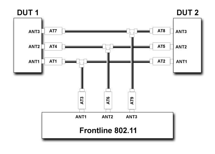
The above test setup if for 3X3 MIMO 802.11 devices. If not testing this configuration, the ANT3 connection to the DUTs and the ComProbe 802.11 is not used.
Test Process
After connecting DUT1, DUT2, and the Frontline 802.11 , follow these steps to capture WiFi data.
- Establish data transmission between DUT 1 and DUT 2.
- Begin capture of the data with the Frontline 802.11 .
- Conduct protocol analysis with the Frontline software on the personal computer or save the capture file for future analysis.