Connecting for HCI/WCI-2 & Logic Capture
To capture UART data at the Bluetooth Host Controller processor interface using a wired connection:
Note: SPI and SDIO capture is currently not available.
Connect an HCI Pod to the bottom of the Sodera unit in POD 1 or POD 2.
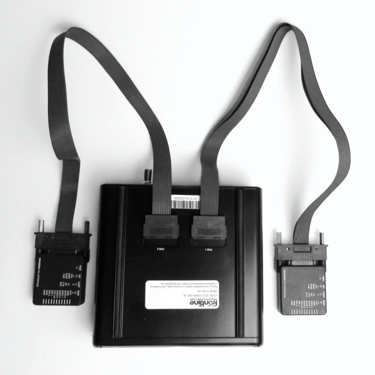
HCI Pods Installed on Sodera
Attach the HCI Flying Lead assembly to the end of the HCI Pod. The connector is keyed to ensure proper installation.

HCI Pod with Flying Lead Assembly

Installing the Flying Lead Assembly on the HCI Pod
- Attach an appropriate Flying Lead Assembly micro-clip to the Bluetooth HCI signal test point in accordance with the following table.
| Transport Layer | Pin | Wire Color | ||
|---|---|---|---|---|
| SPI | UART | SDIO | ||
| CLK | CLK | 1 | Yellow | |
| MISO | TX | CMD | 2 | White |
| MOSI | RX | DATA 0 | 3 | White |
| CSB | CTS | DATA 1 | 4 | White |
| RTS | DATA 2 | 5 | White | |
| DATA 3 | 6 | White | ||
| VIO LVL | VIO LVL | 7 | Red | |
| DIG 1 | 8 | Green | ||
| DIG 2 | 9 | Green | ||
| GND | GND | 10 | Black | |
| GND | GND | 11 | Black | |
-
To remove the Flying Lead Assembly from the HCI Pod, depress the release key on the Flying Lead Assembly.
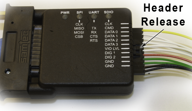
Flying Lead Assembly Header Release
Successful HCI UART capture requires the following Pod connections.
| Signal Name | Pin | Wire Color | Comment |
|---|---|---|---|
| TX | 2 | White | Connect to the Device Under Test (DUT) TX pin. |
| RX | 3 | White | Connect to the DUT RX pin. |
| VIO LVL | 7 | Red | I/O voltage reference that designates the threshold for a logic level "1".. The VIO LVL minimum voltage is 1.65 Vdc. The supplied voltage needs to be the DUT logic signal level that designates a logic level "1". Some DUTs will have a VIO signal/tap. If a VIO tap is not available, use the DUT rail/power supply (Vcc/Vdd). If an I/O reference tap is a available, use that as the VIO LVL source. |
| GND | 10 | Black | Either one of these pins can be used to connect the DUT ground to the HCI pod. |
| GND | 11 | Black |