Connecting for USB Capture
The HCI USB connectors are located on the Sodera rear panel connectors (see "Rear Panel Connectors"). USB testing is normally performed by capturing the USB traffic between a USB device and a host computer or controlling device. In the image below we see the normal configuration of a Bluetooth dongle connected to the USB port of a laptop computer. To capture the USB traffic, the Sodera unit is placed between the dongle and laptop computer. Any traffic between the devices is captured through the Sodera HCI interface.
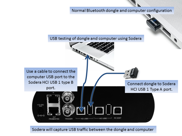
Example: Sodera HCI USB Capture Setup
The HCI USB 1 connectors use the same Sodera unit internal interface as the Sodera HCI POD1 UART pins. Likewise the HCI USB 2 connectors use the same internal interface as the Sodera HCI POD2 UART pins. Therefore you cannot simultaneously capture USB and UART on the "1" interface or on the "2" interface. You can simultaneously capture from the HCI USB 1 connectors and the HCI POD2 UART pins and vice versa. Refer to "Menu".